The rapid transition toward 800V and 1200V architectures in electric vehicle (EV) drivetrains and grid-scale energy storage has pushed traditional packaging materials beyond their physical limits. Engineers working with silicon carbide (SiC) and gallium nitride (GaN) wide-bandgap semiconductors consistently encounter a critical bottleneck: the surrounding passive components and structural mounts degrade rapidly under the immense thermal and electrical stress these new chips generate.
When operating junction temperatures routinely exceed 175°C, standard FR-4 printed circuit boards, epoxy potting compounds, and engineered plastics begin to experience carbonization, leading to catastrophic short circuits and thermal runaway. Addressing this requires a fundamental shift away from organic polymers toward inorganic structural ceramics.

Designing high-power inverters requires solving two fundamentally opposing physical requirements: the system must rapidly pull heat away from the semiconductor die, while simultaneously providing absolute electrical isolation to prevent high-voltage arcing. Most materials that are good conductors of heat (like copper or aluminum) are also excellent conductors of electricity. Conversely, excellent electrical insulators (like PTFE or epoxy) act as thermal blankets, trapping heat and destroying the device.
Technical ceramics bridge this gap. To quantify this advantage, we must evaluate the thermal conductivity against the dielectric strength of various packaging substrates under operational conditions.
Table 1: Substrate Material Performance Metrics at 200°C
| Material Specification | Thermal Conductivity (W/m·K) | Dielectric Strength (kV/mm) | Coefficient of Thermal Expansion (ppm/°C) | Max Continuous Temp (°C) |
| Standard FR-4 PCB | 0.25 | 15 - 20 | 14.0 - 17.0 | 130 |
| Polyimide (PI) Film | 0.12 | 150 (thin film) | 20.0 - 40.0 | 250 |
| Boron Nitride (BN) | 30.0 | 35 | 1.0 - 4.0 | 1000 |
| 96% Alumina (Al₂O₃) | 24.0 | 15 | 7.0 - 8.0 | 1500 |
| Aluminum Nitride (AlN) | 170.0 | 15 | 4.5 | 1000 |
As the data illustrates, while polymers offer high dielectric strength at room temperature, their thermal conductivity is practically nonexistent. When engineers integrate an Alumina Ceramic Insulator between the heat-generating SiC mosfet and the liquid-cooled aluminum chassis, they achieve a thermal pathway that is roughly 100 times more efficient than a standard polymer interface pad, while safely blocking up to 15,000 volts per millimeter of thickness.
The internal componentry is only as secure as its external connections. In multi-megawatt industrial drives or DC fast-charging stations, the power cables carry hundreds of amps. The junction points where these heavy-gauge cables meet the internal busbars are highly susceptible to micro-vibrations and thermal cycling.
Over time, this mechanical movement causes the fastening bolts to lose torque, increasing contact resistance. Increased resistance generates localized heat, often pushing the connection node well above 200°C. If a standard polyamide or phenolic terminal block is used, this sustained heat causes the polymer outgassing and surface carbonization. Once a microscopic carbon track forms across the surface of the plastic, high-voltage electricity will bypass the air gap, resulting in a destructive arc flash.
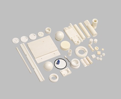
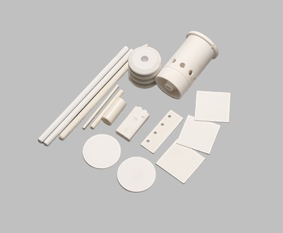
Upgrading the power routing infrastructure to utilize a dedicated Ceramic Terminal Block completely eliminates this failure mode. Made from densely sintered steatite or high-purity alumina, these components contain zero organic compounds. They cannot carbonize, they do not outgas, and their dielectric properties remain entirely stable even if the metal conductors they hold glow red-hot due to an overcurrent fault. Furthermore, their extreme compressive strength allows assembly technicians to apply significantly higher torque to the fastening hardware, reducing the initial risk of high-resistance joints.
Beyond gross thermal failure, a more insidious enemy in power electronics is thermomechanical fatigue. When a device powers on, it heats up and expands; when it powers off, it cools and contracts. If the materials bonded together have vastly different rates of expansion, massive shear forces tear at the solder joints and wire bonds.
Consider a silicon die mounted to a copper baseplate. Silicon has a Coefficient of Thermal Expansion (CTE) of roughly 2.6 ppm/°C, while copper expands at 16.5 ppm/°C. Direct bonding leads to rapid delamination.
Relative Shear Stress Generation Over 10,000 Thermal Cycles (-40°C to +150°C):
Silicon to Copper Interface: 100% (Baseline - High Failure Rate)
Silicon to Organic Substrate (FR4): 85% (Moderate to High Failure Rate)
Silicon to Alumina Ceramic Interface: 22% (Low Failure Rate)
Silicon to Aluminum Nitride Interface: 8% (Negligible Failure Rate)
By utilizing an intermediate Alumina Ceramic Part—specifically a Direct Bonded Copper (DBC) or Active Metal Brazed (AMB) ceramic substrate—engineers create a vital mechanical buffer. The ceramic acts as a rigid, thermally stable foundation. Its CTE of 7.4 ppm/°C sits comfortably between the semiconductor die and the metal heat sink, absorbing the dimensional changes and protecting the fragile solder layers from fracturing over the vehicle's 15-year required lifespan.
Migrating to ceramic solutions requires discipline in mechanical design. Unlike metals, which yield and deform plastically before breaking, or polymers, which flex, ceramics are completely rigid. They possess incredibly high compressive strength (often exceeding 2000 MPa) but relatively low tensile strength.
When designing custom ceramic mounts, standoff insulators, or housing components, engineers must avoid sharp internal corners, which act as stress concentrators. A typical CNC-machined metal part might feature sharp 90-degree internal radii; transferring this exact CAD file to a ceramic manufacturer will result in parts that fracture during the sintering process or fail under operational vibration.
All internal corners must be designed with generous radii (minimum R1.0 mm). Furthermore, point-loading must be avoided. When clamping a ceramic component into a metal chassis, compliant interfaces, such as thin graphite foils or soft metal gaskets (like indium or annealed copper), should be placed between the hard ceramic and the metal fasteners to distribute the compressive load evenly across the surface.
The primary resistance to adopting structural ceramics in electrical engineering is the perceived piece-price penalty. A precision-ground ceramic insulating plate may carry a unit cost five to ten times higher than an injection-molded plastic equivalent.
However, evaluating material selection strictly through the lens of initial Bill of Materials (BOM) cost ignores the realities of warranty claims and field service operations. In offshore wind turbines or aerospace applications, the cost of replacing a single burnt-out polymer insulator is astronomical, factoring in specialized labor, travel logistics, and system downtime. Replacing organic materials with inorganic ceramics shifts the engineering strategy from planning for inevitable degradation to designing for the absolute physical lifespan of the surrounding metal and silicon.
Precision engineering requires acknowledging that high-voltage and high-heat environments actively destroy organic chemistry. Relying on materials whose fundamental atomic structure remains inert regardless of the thermal or electrical load applied is the most reliable method for stabilizing high-power infrastructure.

24/7 Call Service +8618018373518
Email : yxshenxing88@vip.163.com
Address : No. 2022, Baoyang Road, Chuanbu Industrial Zone, Yixing City, Wuxi City, Jiangsu Province


 2025-10-14
 2025-10-14
blog Xml Privacy Policy Sitemap
Copyright @ 2026 Yixing Shenxing Technology Co., Ltd. All Rights Reserved.
 Network Supported
leave a message
Scan to wechat :

Scan to whatsapp :